
How to Simplify and Improve Schematics
Example: Boeing 727 Electrical Power Distribution
|
Figure 1. Original Boeing electrical power distribution
for B-727 (Flight crew system training)
|
 |
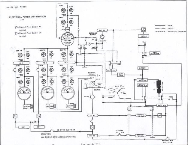 |
This is an example where the designers did not fully understand the technical backgrounds of their intended target audience, pilots. The original schematic is part of Boeing 727 electrical system ground school course for pilots to familiarize flight crews to the various electrical systems on B-727. The left side of the original schematic is clear and self-explanatory. That part of the illustration is almost identical to the switches and gauges on an actual flight engineer's panel. It is the right side of the schematic that can be confusing to many pilots. Perhaps the designers wanted to produce a simplified version of the actual B-727 electrical power distribution while maintaining the schematic "electrically correct", i.e. correct symbols, etc. That's where the real problem lies. Unless a person is familiar with relevant electrical components and the corresponding symbols, the right side of the schematics is quite difficult to understand. Pilots in general do not have, nor is it required to have, that kind of background. It can be very difficult to follow the power distribution from one bus to another. The symbolic representation of relays can hinder students from following the various paths the power is supplied and distributed under normal conditions and in emergency situations such as loss of all generators where battery supply (standby) is the only power available. At first glance our improved schematic looks even more
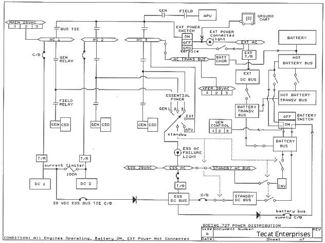
cluttered that the original one. There is an explanation for it. Before
we simplify any schematic, we'll make sure that there aren't any errors
or anything pertinent missing from the schematic. In this case there were
several parts missing that we felt needed to be included (Generator
Control, XFER 28VAC, MAIN
28VAC). Therefore, there are now more system
parts on our schematic. Also, we have corrected some errors that we found
on the original schematic. We have increased the size of some of the buses
(boxes) to emphasize the importance of those components. |
|
Figure 2. Simplified and corrected B-727 electrical
power distribution (Flight crew system training)
|
|
|